Building a game board is pretty straightforward, although getting everything lined up can be a challenge. Here you’ll find all the information needed to design and build your own game board. The below instructions assume a board of 12×12 spaces, adjust as needed.
Materials
- High energy magnetic tape (~160 feet)
- 1/2 inch MDF: Medium Density Fiberboard (~63 inches square)
- Epoxy or superglue (such as Loctite)
- Latex primer or paint
- 3/8 inch by 1/6 inch neodymium magnets (144)
Recommended Tools
- A table saw, or a circular saw and cutting guide (or a helpful lumberyard/hardware store employee)
- A router with a 1/2 inch strait cut bit and a 1/4 inch strait cut bit
- Two C-clamps or Bessy clamps
- Tape measure and/or measuring stick
- Carpenter’s square, framing square, or speed square
Assembly
Make sure that you are familiar with how to use these tools safely or are working with someone who does, and use proper safety equipment; these tools are potentially dangerous and as cool as RoboRukus is, it’s not worth losing fingers for it!
Making the Board Squares
A standard RoboRally board consists of a grid of 12×12 squares. For RoboRuckus each space should be at least 5″ (inches) square, so a standard board would be 60 square inches. However, to make sure the robots have plenty of room inside each space, making the spaces 5-1/4″ square is a good idea, which makes the overall board 63″ square.
If you have the room, you can make one large board, but to make the board more portable and easier to store it can be divided into nine smaller pieces, each 21″ square.
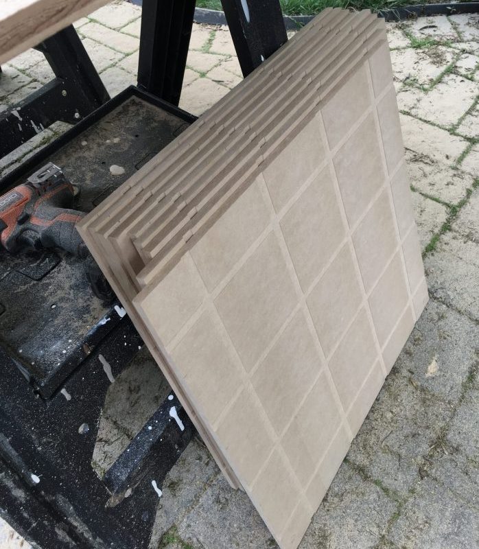
First, cut your MDF into nine 21″ by 21″ squares using the table saw or circular saw. It’s very important to make sure the board pieces are exactly square and exactly 21″ on a side; if the pieces aren’t square and true the magnetic strip won’t line up and your robots won’t navigate correctly. Make sure to account for the kerf, or the width of the wood that the saw blade removes every time it cuts. If you just measure out four lines 21″ inches apart your last square could be 3/8 of an inch shorter than your first one.
Alternatively, your local hardware store or lumberyard may offer cutting services for a nominal fee. While these services are fast and easy, you should make sure they’re accounting for the kerf of the blade, as mentioned above.

Next, draw a line across a board square 2-5/8″ from any edge. This is going to be the center of where your first strip of magnetic tape will go, and again it has to be marked accurately in order to line up with the other board squares. Mark three more lines at 5-1/4″ intervals from the first. This should result in a line 2-5/8″ from either edge and two more lines evenly spaced 5-1/4″ apart between them in the center. Once you’ve finished this, turn your square ninety degrees and repeat this process. You’ll end up with an evenly spaced grid that, when it’s placed next to the other board pieces, will have a bunch of squares spaced 5-1/4″ center-to-center. Repeat this process for the other eight board squares. We found the easiest thing to do was to make two marking guides, both 21″ long. Cut one to 2-5/8″ wide and the other to 5-1/4′ wide. If you cut these correctly you can use them to make accurate strait lines over and over again on your board squares.
Next install the 1/2″ strait cut bit into your router. Measure how thick your magnetic tape is and set the depth of cut on the router to that thickness. Ours was 1/16″, but yours may vary so be sure to measure. Now comes the part where you’ll have to do some figuring: You need to determine how far the edge of your router’s base is from the center of the bit. To do this, measure the router base from one edge to the other strait across the middle. Halve this measurement and write it down. You’re going to use this measurement to place a routing guide (a strait piece of scrap wood) exactly one half the width of your router’s base away from one of the grid lines you drew previously. The routing guide will let you route out a 1/2″ channel exactly centered on the grid you drafted out in the previous step. This channel is where you’re going to lay the magnetic tape.

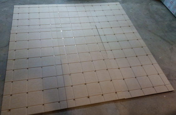
Lay your board square on your work surface with the grid side up, then lay your routing guide parallel to a grid line and “half of the router base” distance away from the line and clamp the guide down; it’s best to start at one edge and work your way across. Start the router and run it along the routing guide, cutting a channel exactly big enough for your tape to lay in. Repeat this process for the all the other grid lines until you have a grid of channels evenly spaced across the surface of your board. Do this again for the rest of your board squares. This process of measuring, marking, clamping, and routing can get tedious, so you might want to make a routing jig (a frame or guide attached to your bench) to make the process much faster. Making a jig is an article all by itself, so it won’t be covered here, but however you do it, route the channels into all nine board sections.
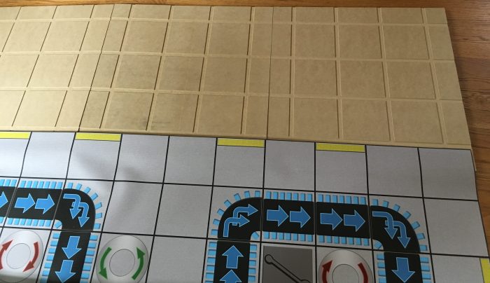
You’re almost done, but there’s a little more work to do before you can start laying tape into the channels. Each intersection on the grid has to have a neodymium magnet embedded under the magnetic tape. To do this, change the router from the 1/2″ to the 1/4″ bit. Now measure the thickness of the magnets and add that to the thickness of the magnetic tape that you used in the last step (alternately, measure the thickness of the tape and magnet together). Set the router’s depth to this measurement and freehand a pocket big enough to accept the neodymium in the center of every intersection. Don’t worry about making perfect circles, just make sure your circles don’t get outside the channels. If you have a vinyl mat printed, you can lay that on the completed board sections to check the fit.
Installing the Magnets
The first step is to glue one of the neodymium magnets into each of the routed pockets at the intersection of the channels. It’s important to make sure the same pole (face) of the magnet is facing up for every magnet. While which side of the magnet you chose doesn’t really matter, to use the same one we use you can take a single magnet and lay it flat on a surface, then move one of the magnetometers slowly over it while reading the Z-axis value (you can follow these instructions for setting up the magnetometer). The value should drop and go more negative as it approaches magnet, if it goes more positive first then drops towards negative, flip the magnet over. If you use a different face than we did, the robot control program might need some tweaking.
Once you’ve decided on a face to use, place a drop of glue or epoxy in each pocket and press a magnet into the glue until every intersection has a magnet. Repeat this for all nine of the board squares.

Installing the magnetic tape requires the same attention to orientation as the neodymium magnets. The way it’s currently set up, the white tape side of the magnet strip faces up, if you’d like to reverse this, you’ll need to alter the robot movement code, which isn’t recommended unless you’re confident in your understanding of the code.
To install the strips, cut a length long enough to reach from one board edge to the other. You might get cleaner results by cutting the piece slightly long and trimming it once it’s installed. Try pressing the strip into the channel and make sure it’s flush and not bulging up anywhere; you can try to flatten any troublesome areas by pressing the edge in with a screw driver, or trying to flatten it with a rolling pin or similar item. If the channel is too tight, you can trim the tape lengthwise with scissors or a paper cutter to make it narrower, else if the channel is too lose a few dollops of glue can help hold the strip in place.
Repeat this for the next three strips until you have four parallel strips running across the board. Carefully cut smaller strips and fill in the perpendicular channels, butting the smaller strips up against the longer strips as exactly as you can; the idea is to have the robot “see” each direction as one continuous strip. Repeat this for all nine board squares and then peel the white protective tape off of all the strips.


Once the magnets are installed you’ll want to prime or paint the board. The board pieces need to be sealed against moisture so that they don’t warp over time (plus they just look neater). Don’t use a heavy coat and make sure to cover the top, sides, and bottom. Painting only one side might cause exactly the kind of warping that we’re trying to avoid.
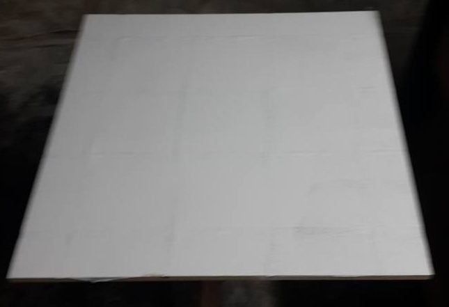
Painting was the last step, so sit back and enjoy your craftsmanship as your bots raise a ruckus down on the Factory Floor! Patience and accuracy are going to be your best friends while you’re working on this, so make sure not to rush through any of the processes. If you do this correctly you’ll be able to lay your board squares down in any position and turned any direction and still have all the lines match up.
The Game Mat
A game mat printed on vinyl provides an excellent surface for the robots to drive on, as well as providing the obstacles the robots need to navigate. For copyright reasons, we currently don’t have any printable boards that can be shared (though you can find an unofficial list of official RoboRally boards here), however you can find all our custom assets for the various board elements in the GitHub repository.
The Board Maker (detailed below) can be used to create a print-ready board image, or, using your favorite image editing program, you can lay out a grid of squares to match your board. You can then add the board elements in whatever pattern you’d like. Once you’re happy with your board, you can have it printed at a site like printmoz.com. You can print as many boards for the game as you want, and can print them double-sided for more boards on less vinyl. It’s a good idea to include a red dot or some other mark in the lower left corner of your board to indicate the [0, 0] (origin) coordinate.
The flags can be printed on reusable stickers purchased from a place like Sticker Genius (4″x4″ is the recommended size) using the assets in the GitHub repository, or they can be printed directly on the board.
The Board Maker
The board maker interface can be used to create boards that will automatically be added to the server, as well print-ready images that can be sent to a print shop to create a vinyl mat as described above. This requires a running game server as described in Setting Up the Game, or running the server from Visual Studio or Visual Studio Code. Connect the server Setup screen and chose the “Board Maker” button to get to the Board Maker screen.


Enter a board name and size in number of squares. When the size is entered a blank board layout will be shown on the screen. Board elements can be dragged and dropped onto the board wherever you want them. Supported elements can be rotated by clicking on the placed element. Elements can be moved to another square after being placed or dragged to the trashcan icon in the upper right to be removed. Only one element can be added to any board square with the exception of walls, lasers, and beams which can be stacked on top of other elements, though not vice versa.
When your board is finished, clicking the “Make Board” button will send the new board to the server. Be patient, it can take several minutes for the server to finish generating the board images. When the server is finished, the Board Maker screen will be refreshed. You can edit an existing board by selecting it from the drop down menu and updating it when finished with the “Make Board” button. The board can be deleted using the “Delete Board” button; the board layout will not be cleared so you can still save it as a different board if desired. A print-ready image of the board can be downloaded by clicking the “Get Printable Image” button, and a red dot is automatically added to the lower left corner of the images to aid in orientation.
Board Elements
The following board elements can be added to the board layout:
- Left turntable: Adds a counter-clockwise turntable to the board.
- Right turntable: Adds a clockwise turntable to the board.
- Conveyor: Adds a straight conveyor section to the board.
- Express conveyor: Adds a straight express conveyor section to the board.
- Right conveyor curve: Adds a right-handed conveyor curve to the board.
- Right express conveyor curve: Adds a right-handed express conveyor curve to the board.
- Left conveyor curve: Adds a left-handed conveyor curve to the board.
- Left express conveyor curve: Adds a left-handed express conveyor curve to the board.
- Corner: Purely aesthetic, this corner element is equivalent to two right-angled walls in the same square.
- Wall: Adds a wall element to the board.
- Lasers (1, 2, or 3 emitters): Adds a laser element to the board with the specified laser power.
- Laser beams (1, 2, or 3 beams): Purely aesthetic, it is not necessary to add these beams to the board as this is done automatically when the sever generates the board images. However, it can be useful to place the beams on the board to help plan the layout and visualize the final image.
- Pit: Adds a pit element to the board.
- Wrench: Adds a wrench element to the board.
Limitations
The board maker has the following limitations, if you wish to work without them a board can be manually added to the sever as described in the next section.
Maximum size and memory usage: The maximum board size you can make depends on the amount of RAM available in your system to render the images. While the CLR will render images for boards of any size, creating a board that requires significantly more RAM than your system has will take significantly longer and could result in errors, especially for the downsized web image. The Chop Shop board, for instance, requires about 4 GB of RAM to create.
Corner rendering: When loading saved boards, corners will not be added to the layout. Instead, two right-angled walls will be rendered in place of the corner. If you want a corner in the place it’s important to remember to remove the two walls and replace them with a corner before submitting the board to the server. While it has no practical or game play effect on the board, it will change the appearance of the generated board images.
Manually Adding the Board to the Server
You can manually create a board and add it to the game server if you’d rather not use the Board Maker or don’t want to be subject to its limitations. The first step is to encode all the important information about your board in a JSON file (a plain text file with a .json extension).
The first part of the file looks like this:
"name": "Chop Shop",
"size": [ 11, 11 ],
You should change the name and size of the board to match yours. The size is the zero-ordered number of spaces [x, y] in your board, so if your board is 12×12 spaces, use [11, 11]. The rest of the file contains the board elements, which should match the ones on your printed board. For example:
"wrenches": [
    [ 0, 0 ],
    [ 9, 2 ],
    ...
],
"pits": [
    [ 1, 1 ],
    [ 9, 5 ],
    ...
],
"turntables": [
    {
      "location": [ 5, 2 ],
      "dir": "right"
    },
    {
      "location": [ 6, 2 ],
      "dir": "left"
    },
    ...
],
"lasers": [
    {
      "start": [ 10, 1 ],
      "end": [ 10, 1 ],
      "strength": 3,
      "facing": "NEG_Y"
    },
    {
      "start": [ 7, 2 ],
      "end": [ 2, 2 ],
      "strength": 1,
      "facing": "NEG_X"
    },
    ...
],
"conveyors": [
    {
      "location": [ 5, 0 ],
      "entrance": "Y",
      "exit": "NEG_Y"
    },
    {
      "location": [ 6, 0 ],
      "entrance": "NEG_Y",
      "exit": "Y"
    },
    ...
],
"expressConveyors": [
    {
      "location": [ 0, 3 ],
      "entrance": "X",
      "exit": "NEG_X"
    },
    {
      "location": [ 1, 3 ],
      "entrance": "X",
      "exit": "NEG_X"
    },
    ...
],
"walls": [
    [
      [ 2, 0 ],
      [ 2, -1 ]
    ],
    [
      [ 4, 0 ],
      [ 4, -1 ]
    ],
    ...
]
The above example shows two of each of the supported elements (more could be added where the … are). If you don’t have any of a particular element, leave the space between the brackets for that element blank, e.g. "lasers": [ ],. The currently supported board elements are (though more may be added in the future):
- wrenches – This element consist of an array of
[x, y]coordinates for each wrench on the board. - pits – Much the same as wrenches, this is an array of
[x, y]coordinates for each pit on the board. - turntables – This element consists of the
[x, y]coordinate of each turntable and the direction each turntable rotates (right for clockwise, left for counter-clockwise). - lasers – This element consists of the starting
[x, y]coordinate of each laser, the ending [x, y] coordinate of the laser, the number of beams (i.e. the damage it does), and the direction the laser fires towards. - conveyors – This element consists of the
[x, y]coordinate of each conveyor piece on the board, the side of the square the conveyor enters (starts) on, and the side of the square the conveyor exits (ends) on. Note: Merging conveyor spaces are not currently supported. - expressConveyors – The same as conveyors but for the express conveyor spaces.
- walls – This element consists of the
[[x1, y1], [x2, y2]]coordinates of the two spaces each wall stands between, the[x1, y1]coordinate is the one the wall actually occupies.
A full example of the JSON encoding of the RoboRally board Chop Shop is included at the bottom of this page.
Save your board file with the same name as your board, but with the spaces removed, so Chop Shop becomes ChopShop.json; be sure to match the capitalization. Now put your JSON file in the sever directory ~/RoboRuckus/GameConfig/Boards/.
Lastly, you should save a PNG image of your board, with the same name as your board file (e.g. ChopShop.png), and put it in the server directory ~/RoboRuckus/wwwroot/images/boards/.
When you next start a game you should see your board in the selection menu, now go play it!
{
  "name": "Chop Shop",
  "size": [ 11, 11 ],
  "wrenches": [
    [ 0, 0 ],
    [ 9, 2 ],
    [ 5, 5 ],
    [ 4, 9 ],
    [ 11, 11 ]
  ],
  "pits": [
    [ 1, 1 ],
    [ 9, 5 ],
    [ 6, 7 ],
    [ 3, 9 ],
    [ 9, 9 ]
  ],
  "turntables": [
    {
      "location": [ 5, 2 ],
      "dir": "right"
    },
    {
      "location": [ 6, 2 ],
      "dir": "left"
    },
    {
      "location": [ 8, 4 ],
      "dir": "right"
    },
    {
      "location": [ 8, 5 ],
      "dir": "left"
    },
    {
      "location": [ 4, 6 ],
      "dir": "left"
    },
    {
      "location": [ 5, 8 ],
      "dir": "right"
    },
    {
      "location": [ 8, 8 ],
      "dir": "left"
    }
  ],
  "lasers": [
    {
      "start": [ 10, 1 ],
      "end": [ 10, 1 ],
      "strength": 3,
      "facing": "NEG_Y"
    },
    {
      "start": [ 7, 2 ],
      "end": [ 2, 2 ],
      "strength": 1,
      "facing": "NEG_X"
    },
    {
      "start": [ 1, 5 ],
      "end": [ 1, 3 ],
      "strength": 1,
      "facing": "NEG_Y"
    },
    {
      "start": [ 8, 6 ],
      "end": [ 8, 3 ],
      "strength": 2,
      "facing": "NEG_Y"
    },
    {
      "start": [ 10, 7 ],
      "end": [ 10, 9 ],
      "strength": 1,
      "facing": "Y"
    },
    {
      "start": [ 6, 8 ],
      "end": [ 4, 8 ],
      "strength": 1,
      "facing": "NEG_X"
    }
  ],
  "conveyors": [
    {
      "location": [ 5, 0 ],
      "entrance": "Y",
      "exit": "NEG_Y"
    },
    {
      "location": [ 6, 0 ],
      "entrance": "NEG_Y",
      "exit": "Y"
    },
    {
      "location": [ 5, 1 ],
      "entrance": "Y",
      "exit": "NEG_Y"
    },
    {
      "location": [ 6, 1 ],
      "entrance": "NEG_Y",
      "exit": "X"
    },
    {
      "location": [ 7, 1 ],
      "entrance": "NEG_X",
      "exit": "X"
    },
    {
      "location": [ 8, 1 ],
      "entrance": "NEG_X",
      "exit": "X"
    },
    {
      "location": [ 9, 1 ],
      "entrance": "NEG_X",
      "exit": "X"
    },
    {
      "location": [ 11, 1 ],
      "entrance": "NEG_X",
      "exit": "X"
    },
    {
      "location": [ 9, 3 ],
      "entrance": "X",
      "exit": "NEG_X"
    },
    {
      "location": [ 10, 3 ],
      "entrance": "X",
      "exit": "NEG_X"
    },
    {
      "location": [ 11, 3 ],
      "entrance": "X",
      "exit": "NEG_X"
    },
    {
      "location": [ 4, 5 ],
      "entrance": "NEG_Y",
      "exit": "Y"
    },
    {
      "location": [ 0, 6 ],
      "entrance": "X",
      "exit": "NEG_X"
    },
    {
      "location": [ 1, 6 ],
      "entrance": "X",
      "exit": "NEG_X"
    },
    {
      "location": [ 2, 6 ],
      "entrance": "X",
      "exit": "NEG_X"
    },
    {
      "location": [ 3, 6 ],
      "entrance": "X",
      "exit": "NEG_X"
    },
    {
      "location": [ 5, 6 ],
      "entrance": "Y",
      "exit": "X"
    },
    {
      "location": [ 6, 6 ],
      "entrance": "NEG_X",
      "exit": "X"
    },
    {
      "location": [ 7, 6 ],
      "entrance": "NEG_X",
      "exit": "X"
    },
     {
      "location": [ 5, 7 ],
      "entrance": "Y",
      "exit": "NEG_Y"
    },
    {
      "location": [ 0, 8 ],
      "entrance": "NEG_X",
      "exit": "X"
    },
    {
      "location": [ 1, 8 ],
      "entrance": "NEG_X",
      "exit": "X"
    },
    {
      "location": [ 2, 8 ],
      "entrance": "NEG_X",
      "exit": "X"
    },
    {
      "location": [ 9, 8 ],
      "entrance": "NEG_X",
      "exit": "X"
    },
    {
      "location": [ 10, 8 ],
      "entrance": "NEG_X",
      "exit": "X"
    },
    {
      "location": [ 11, 8 ],
      "entrance": "NEG_X",
      "exit": "X"
    },
    {
      "location": [ 1, 9 ],
      "entrance": "Y",
      "exit": "X"
    },
    {
      "location": [ 2, 9 ],
      "entrance": "NEG_X",
      "exit": "X"
    },
    {
      "location": [ 5, 9 ],
      "entrance": "Y",
      "exit": "NEG_Y"
    },
    {
      "location": [ 8, 9 ],
      "entrance": "Y",
      "exit": "NEG_Y"
    },
    {
      "location": [ 1, 10 ],
      "entrance": "Y",
      "exit": "NEG_Y"
    },
    {
      "location": [ 5, 10 ],
      "entrance": "Y",
      "exit": "NEG_Y"
    },
    {
      "location": [ 8, 10 ],
      "entrance": "Y",
      "exit": "NEG_Y"
    },
    {
      "location": [ 1, 11 ],
      "entrance": "Y",
      "exit": "NEG_Y"
    },
    {
      "location": [ 5, 11 ],
      "entrance": "Y",
      "exit": "NEG_Y"
    },
    {
      "location": [ 8, 11 ],
      "entrance": "Y",
      "exit": "NEG_Y"
    }
  ],
  "expressConveyors": [
    {
      "location": [ 0, 3 ],
      "entrance": "X",
      "exit": "NEG_X"
    },
    {
      "location": [ 1, 3 ],
      "entrance": "X",
      "exit": "NEG_X"
    },
    {
      "location": [ 2, 3 ],
      "entrance": "X",
      "exit": "NEG_X"
    },
    {
      "location": [ 3, 3 ],
      "entrance": "X",
      "exit": "NEG_X"
    },
    {
      "location": [ 4, 3 ],
      "entrance": "X",
      "exit": "NEG_X"
    },
    {
      "location": [ 5, 3 ],
      "entrance": "X",
      "exit": "NEG_X"
    },
    {
      "location": [ 6, 3 ],
      "entrance": "X",
      "exit": "NEG_X"
    },
    {
      "location": [ 7, 3 ],
      "entrance": "X",
      "exit": "NEG_X"
    },
    {
      "location": [ 2, 4 ],
      "entrance": "Y",
      "exit": "NEG_Y"
    },
    {
      "location": [ 0, 5 ],
      "entrance": "NEG_X",
      "exit": "X"
    },
    {
      "location": [ 1, 5 ],
      "entrance": "NEG_X",
      "exit": "X"
    },
    {
      "location": [ 2, 5 ],
      "entrance": "NEG_X",
      "exit": "NEG_Y"
    }
  ],
  "walls": [
    [
      [ 2, 0 ],
      [ 2, -1 ]
    ],
    [
      [ 4, 0 ],
      [ 4, -1 ]
    ],
    [
      [ 7, 0 ],
      [ 7, -1 ]
    ],
    [
      [ 9, 0 ],
      [ 9, -1 ]
    ],
    [
      [ 10, 1 ],
      [ 10, 2 ]
    ],
    [
      [ 10, 1 ],
      [ 10, 0 ]
    ],
    [
      [ 0, 2 ],
      [ -1, 2 ]
    ],
    [
      [ 1, 2 ],
      [ 1, 3 ]
    ],
    [
      [ 2, 2 ],
      [ 1, 2 ]
    ],
    [
      [ 7, 2 ],
      [ 8, 2 ]
    ],
    [
      [ 8, 2 ],
      [ 8, 3 ]
    ],
    [
      [ 11, 2 ],
      [ 12, 2 ]
    ],
    [
      [ 0, 4 ],
      [ -1, 4 ]
    ],
    [
      [ 11, 4 ],
      [ 12, 4 ]
    ],
    [
      [ 1, 5 ],
      [ 1, 6 ]
    ],
    [
      [ 3, 5 ],
      [ 3, 4 ]
    ],
    [
      [ 3, 5 ],
      [ 4, 5 ]
    ],
    [
      [ 5, 6 ],
      [ 5, 5 ]
    ],
    [
      [ 8, 6 ],
      [ 8, 7 ]
    ],
    [
      [ 0, 7 ],
      [ -1, 7 ]
    ],
    [
      [ 10, 7 ],
      [ 10, 6 ]
    ],
    [
      [ 11, 7 ],
      [ 12, 7 ]
    ],
    [
      [ 4, 8 ],
      [ 3, 8 ]
    ],
    [
      [ 6, 8 ],
      [ 7, 8 ]
    ],
    [
      [ 0, 9 ],
      [ -1, 9 ]
    ],
    [
      [ 11, 9 ],
      [ 12, 9 ]
    ],
    [
      [ 6, 10 ],
      [ 7, 10 ]
    ],
    [
      [ 10, 10 ],
      [ 10, 9 ]
    ],
    [
      [ 2, 11 ],
      [ 2, 12 ]
    ],
    [
      [ 4, 11 ],
      [ 4, 12 ]
    ],
    [
      [ 7, 11 ],
      [ 7, 12 ]
    ],
    [
      [ 9, 11 ],
      [ 9, 12 ]
    ]
  ]
}